

This product and installation instruction is Courtesy of Gavin Earnshaw from the United Kingdom.
*Note 2-5-2020 - There are some remarks regarding the two studs on the back of the unit not being centered. These are hand made (not machined) so it is difficult to get them centered. Some studs may be more centered than others but this has been tested and should not affect use or installation.
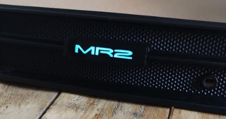
Thank you for purchasing the El Glow Badge for the Toyota MR2 SW20. We hope the item arrives to you safe and anticipate an easy set up for the product and hope you enjoy.
A brief introduction to the making of the reproduction badge was due to the original badge that we had on the car broken and lost power to the neon strip. The badge was then taken to a local plastics company in England UK to see if they could cut a faithful reproduction of the original badge with similar electrical neon components to give the retro look of the early 1990s.
There has been lots of trial and error with different glues, bolts, screws and fitments and we now feel happy that we are there with the first version to be sold to the dedicated and valued MR2 enthusiast. The el glow badge clear logo and gloss black surrounds have been glued using dichloromethane. This liquid chemical melts plastics together and draws out oxygen for water tight finish. The el glow strip has been secured from the inside with a water resistant double sided tape followed by a black epoxy resin with the black back panel attached to close the unit.
The current bolts are a nylon (m6) thread which have been glued using a two part epoxy resin which should hold the badge in place once attached to the rear center panel. The hardware includes 2 x m6 threads and bolts with washers and also includes a transformer converting 12v to make the el glow strip to work.

Installation Guide
Step 1. Screw the threads into the bolts carefully. (DO NOT OVER TIGHTEN)

Step 2. Take off your centre panel from the car, place the wire through the left hand side first, carefully followed by guiding both screw threads.

Step 3. Turn the panel carefully over. Locate your washers and bolts and LOOSLY tighten into place. (DO NOT OVER TIGHTEN AS THIS MAY PUT TOO MUCH STRESS ON THE BADGE)

Step 4. Turn the panel over and adjust the badge and screws so it fits as symmetrical as possible to the panel. (DO NOT OVER TIGHTEN THE BOLTS) Just ensure it is secure to avoid any damage.

Step 5. Plug the el glow wire to the transformer. Locate a positive and negative wire from the rear tail lights or the rear number plate wire and test the connection to ensure the el glow turns on. (Remember you will need to have your car lights from the steering column turned on to test this).
Once you are happy with the connections, connect the wires with either additional clips or solder and use electrical tape for insulation.
Step 6. Bolt up and reattach the center panel and lights together and enjoy!

Additional Supplemental Instructions from Gavin - 3/12/2024
In order to preserve the longevity of this product, we have included two features called a heatsink and a regulator.
The aim of the regulator is to reduce the risk on Amp power surges to maintain a 9v constant supply to the el glow neon strip.
The heatsink attached to the regulator helps to draw additional heat away and keep the item cooler whilst the light is in operation.
Instructions to install.
The regulator simply attached into of the heatsink and is held in place by a small mounting screw.
The regulator has three small metal prongs.

By looking at the picture from left prong to right prong you have:-
Far left prong +I've in. This needs to attached to the positive light loom wire.
Middle prong may be used as an additional earth if required.
Far right prong is +I've out. The red positive wire from the invertor needs to be attached here.
Finally the black negative wire from the invertor needs to attach directly to the negative wire to the light loom to complete the circuit.
It is advised to when wiring up to use insulation tape between all wires and for best results to solder the wires to the heat sink and additional wires.
Before any final fitments, we advise you test the items circuit first.
